


0%
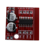
MX1508 Dual H Bridge DC PWM Stepper Motor Driver
₹40.00 (Incl. Tax)
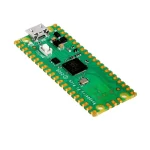
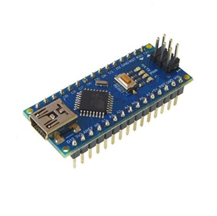
Raspberry Pi Pico Clone
₹280.00 (Incl. Tax)
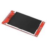
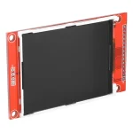
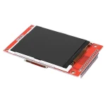
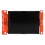
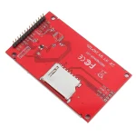
2.8″ TFT LCD Display Module SPI 240×320 Pixels with ILI9341 Driver & SD Card Slot
₹550.00 (Incl. Tax)
1 in stock
7
People watching this product now!
Description
Quick Introduction Upgrade your interface from simple text to full-colour graphics with the 2.8″ TFT LCD Module. Powered by the robust ILI9341 driver, this display delivers a crisp 240×320 resolution with 65K colours. Unlike older parallel displays that hog 10+ pins, this module uses a streamlined 4-Wire SPI interface, leaving plenty of I/O available for your sensors and actuators. It also includes an onboard full-size SD card slot, making it easy to load bitmaps and logs directly from the screen.
Detailed Specifications
- Driver IC:
- Resolution: 240 x 320 Pixels (RGB).
- Interface: 4-Wire SPI (Serial Peripheral Interface).
- Display Size:8-inch Diagonal.
- Color Depth: 18-bit (262K) / 16-bit (65K) Colors.
- Operating Voltage (VCC):3V – 5.0V (Onboard 3.3V Regulator).
- Logic Voltage: 3V ONLY (Not 5V Tolerant).
- Backlight: LED (PWM controllable or 3.3V fixed).
- Storage: Onboard SD Card Slot (SPI).
Quality Advantage & Differentiation: Why choose this SPI TFT?
- Pin Efficiency: By using SPI, you only need 4-5 control pins (SCK, MOSI, CS, DC, RST) compared to the 8-16 pins required by parallel displays.
- Broad Library Support: The ILI9341 is one of the most supported drivers in the maker ecosystem. It works flawlessly with Adafruit_ILI9341, TFT_eSPI (for ESP32), and Ucglib.
- Versatile Power: The onboard voltage regulator allows you to power it from 5V (Arduino) or 3.3V (ESP32/STM32) seamlessly, though logic levels must be handled carefully.
Key Applications & Usage
- IoT Dashboards: Display MQTT data, graphs, and connection status on ESP32 devices.
- Game Consoles: Build retro handheld games using the fast SPI refresh rates (especially with DMA on ESP32).
- Medical Devices: Create clean, readable interfaces for heart rate monitors or digital thermometers.
- Photo Frames: Cycle through bitmaps loaded from the onboard SD card.
What’s Included & Required
- Included: 1x 2.8″ TFT LCD Display Module (SPI).
- Required: Microcontroller (Arduino/ESP32), Jumper Wires, Logic Level Shifter (if using 5V Arduino).
Helpful Tutorials & Resources
- Wiring Guide: Interfacing ILI9341 SPI with Arduino – Guide on wiring with resistors/shifters.
- Library Setup: TFT_eSPI Configuration for ESP32 – High-performance driver setup.
The “Virtual Technician” Support Panel
- ⚠️ CRITICAL SAFETY WARNING:
- 3V Logic Only: The VCC pin can take 5V, but the Data Pins (SCK, MOSI, CS, DC, RST) are 3.3V Logic. Connecting these directly to a 5V Arduino Uno will eventually damage the screen or cause “White Screen” artefacts.
- Solution: Use a Logic Level Converter module or 1.2kΩ/2.2kΩ voltage divider resistors on the data lines.
- Touch Function: This specific SKU is the Non-Touch While the PCB may have pins labelled “T_CLK” or “T_CS”, the touch digitiser glass and XPT2046 controller are likely not installed/active on this economy model.
- Pinout Reference:
- VCC:3V – 5V Power Input.
- GND:
- CS: Chip Select (Low Enable).
- RESET: Reset (Low Active).
- DC/RS: Data/Command Selection.
- SDI (MOSI): SPI Data Input.
- SCK: SPI Clock.
- LED: Backlight (3.3V for ON).
- SDO (MISO): SPI Data Output (Rarely used for display, used for SD card).
Reviews (0)
Ask Us Question About This Product
You may also like…


1.8 Inch SPI TFT LCD Module 128×160 with 4 IO
SKU:
SE69993

Sold out

Related products
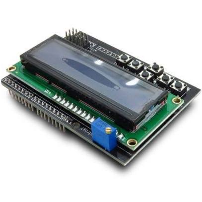
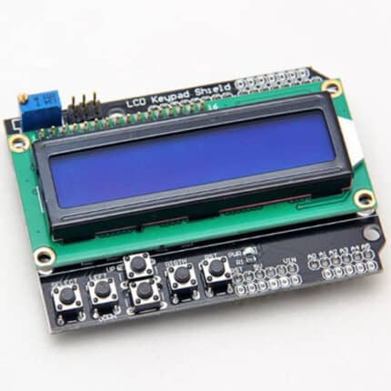
1602 LCD Board Keypad Shield Blue Backlight
SKU:
SE98396


Center Shaft Motor 100 RPM
SKU:
SE79211
Center Shaft Motor 30 RPM
SKU:
SE95895


L293D Motor Driver Shield for Arduino
SKU:
SE79731

NRF24L01PA LNA SMA Wireless Transceiver Antenna
SKU:
SE23193

Robotics Switch Box Enclosure With DPDT Switches
SKU:
SE53959

Sold out
SIM900A – GSM GPRS Module
SKU:
SE43918
Reviews
There are no reviews yet.